

 ALL PLUGINS
 CONTACT
The MLabs AutoCAD Productivity Suite provides production tools for Autodesk AutoCAD users. It includes batch drawing merging, layout-to-model export, Excel table synchronization, raster image embedding, batch plotting, and a built-in Model Context Protocol (MCP) server for connecting AutoCAD with AI assistants.
This guide explains how to configure and use each tool in the suite step-by-step.
1. AutoCAD MCP Server: AI Agents Integration AI Server
The AutoCAD MCP Server enables AI desktop assistants and coding agents (such as Claude Desktop, Google Antigravity, and ChatGPT Desktop) to communicate directly with your running Autodesk AutoCAD session using the open Model Context Protocol (MCP).
Once connected, the AI agent can read drawing properties, query specific entities, frame views, draw geometry, batch update text, and place review annotations through conversational chat.
- Click the MCP Server button on the MLabs ribbon tab.
- Alternatively, type any of these commands in the AutoCAD command line and press Enter:
MLABSMCP,AUTOCADMCP, orMCPSERVER.
1.1. Connecting AutoCAD MCP to AI Agents
The MCP Server management window displays the detected AI assistants installed on your workstation. You can install the server configuration with a single click:
- Open the AutoCAD MCP Server window from the ribbon or command line.
- Under Supported AI Agents, locate your desired assistant:
- Claude Desktop: Writes configuration to
%APPDATA%\Claude\claude_desktop_config.json. - Google Antigravity: Writes configuration to
~/.gemini/config/mcp_config.json. - ChatGPT Desktop: Generates and registers the local plugin manifest.
- Claude Desktop: Writes configuration to
- Click the Install MCP button next to the agent name. The configuration is written automatically.
If your AI agent application (Claude Desktop, Google Antigravity, or ChatGPT Desktop) is currently open or running in the background when you click “Install MCP”, you must completely restart the AI agent (close the application and launch it again). AI agents only load new MCP server definitions upon startup. If you do not restart the AI application, it will not see or recognize the AutoCAD MCP tools.
1.2. Verifying Connection & Status
After restarting your AI agent, you can easily verify the connection:
- In your AI agent’s chat window, type:
Ping AutoCADorCheck AutoCAD connection. - The AI assistant will execute the ping tool and return the current AutoCAD version, active drawing file name, and connection state.
- In the AutoCAD MCP Server window, the status badge will indicate CONNECTED / VERIFIED along with the timestamp of the last agent request.
1.3. Available MCP Tools & Actions
Once configured, the AI assistant can call any of the following tools based on your prompts:
get_active_drawing_info: Returns active drawing title, file path, current space (Model or Layout), and total layer count.get_drawing_summary: Returns coordinate extents (WCS), drawing units, current space, layer list with visibility/freeze states, block definitions, and object counts grouped by type.query_entities: Searches entities by layer name, entity type, or coordinate boundary box. Supports an optional drawing audit to detect text overrides or dimension mismatches.get_entity_details: Retrieves geometric data, vertex coordinates, layer info, and block attributes for specified entity handles.
batch_execute_cad_operations: Executes drafting operations including drawing lines, polylines, circles, arcs, text notes, block insertions, and geometry stretching in an undo group.capture_drawing_view: Takes an image snapshot of the current viewport along with WCS coordinate boundary metadata.zoom_view: Adjusts the AutoCAD view to drawing extents, a specified coordinate boundary, or a center point.manage_text_styles: Lists, creates, or converts text styles with TrueType fonts or SHX fonts.replace_text_in_drawing: Finds and replaces text across text entities, block attributes, multileaders, and dimensions (ideal for drawing translation or terminology updates).add_drawing_annotation: Places revision clouds (RevCloud), multileaders (MLeader), and callout notes on a dedicated annotation layer.
2. Merge Panel: Batch DWG & Layout Conversion
2.1. “Merge Drawings” Command (MSMERGE)
The Merge Drawings command (MSMERGE) combines multiple external DWG files into the active drawing without requiring you to open, copy, and paste each file manually.
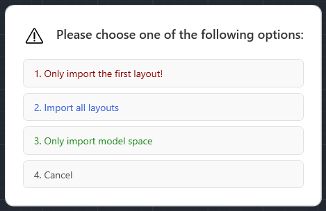
When you execute Merge Drawings, you are presented with three import modes:
- Only import the first layout: Imports only the primary layout tab from each source DWG file. Useful when each DWG represents a single sheet.
- Import all layouts: Imports every layout tab from each selected DWG file into the current drawing. Any duplicate layout names are automatically renamed with incremental numbering.
- Only import model space: Imports all Model Space entities from the selected files into the active drawing’s Model Space at a chosen coordinate location.
How to Use Merge Drawings:
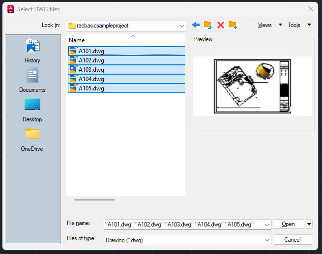
Step 1: Select Files: A file dialog opens allowing you to select the DWG files you want to merge.
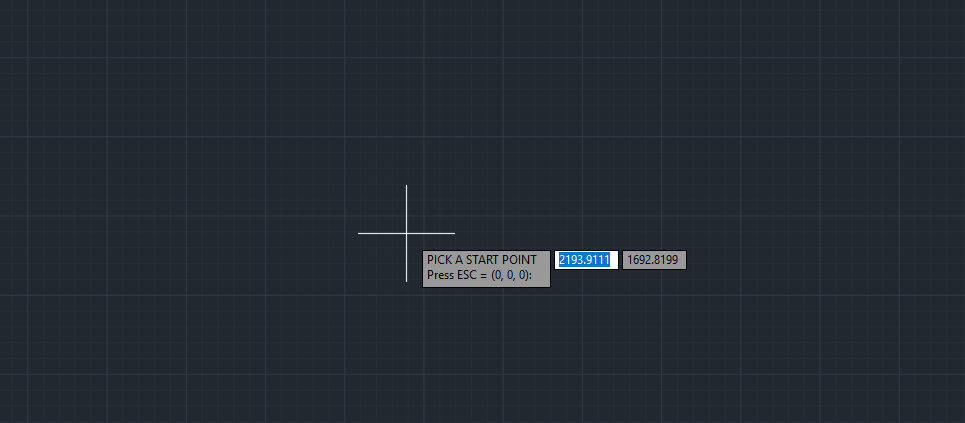
Step 2: Pick Insertion Point: Click in AutoCAD Model Space to set the insertion origin, or press ESC to insert at the default coordinate (0,0,0).
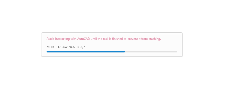
Step 3: Background Processing: A progress window tracks file processing, entity placement, and layer management in real time.
2.2. “Layouts to Model” Command (MsExportLayouts)
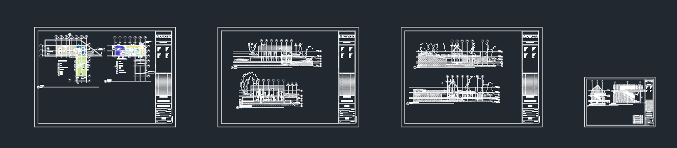
The Layouts to Model command (MsExportLayouts) exports all paper space layouts from the current drawing into Model Space in a new DWG file, arranged neatly side-by-side.
Configuration Settings:
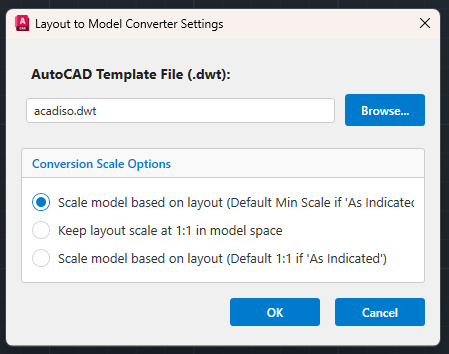
Base AutoCAD Template (.dwt): Select the base template for the exported file. The default is standard acadiso.dwt (Metric) or acad.dwt (Imperial). Click Browse… to use your office custom template.
- Scale model based on layout [Recommended]: Rescales viewport objects according to viewport scale (e.g., 1:50 viewport scaled 50x) so that objects in the exported Model Space measure at true 1:1 real-world size.
- Keep layout scale at 1:1 in model space: Inserts layout objects matching their paper sheet coordinates (e.g., an A1 title block measures 841 × 594 mm).
3. Utilities Panel: Import Excel, ToolBox, Convert Style & Tab Colors
3.1. “Import Excel” to AutoCAD Table (MsImportExcel)
The Import Excel command (MsImportExcel) imports tables from Microsoft Excel spreadsheets directly into native AutoCAD Table entities, preserving formatting and cell alignment.
- Click Import Excel on the ribbon or type
MsImportExcel. - Select your Excel file and check the worksheets you want to import.
- Set the import options:
- Print Area: When checked, reads only the cell range defined as Print Area in Excel. If unchecked or not defined, reads the used data range.
- Layer: Designates the target layer for the table (default:
MS_TABLE). - Text Height: Sets the uniform font height for table cells.
- Click on the drawing to pick the table insertion point.
- Type a scale factor, or press D to dynamically drag and scale the table to your preferred size.
3.2. AutoCAD ToolBox (MSTOOLBOX)
Clicking ToolBox (MSTOOLBOX) opens a quick-utility window containing common CAD drafting helpers:
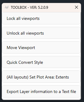
- 🔒 Lock all viewports: Locks every viewport across all layout tabs in the drawing, preventing accidental zooming or panning while drafting in Paper Space.
- 🔓 Unlock all viewports: Unlocks all viewports across all layout tabs.
- 📐 Move Viewport: Shifts the view inside a viewport by picking two reference points in model space, without moving the viewport frame on the paper sheet.
- 🎯 Quick Convert Style: Standardizes properties for currently selected entities only.
- 🖨️ (All layouts) Set Plot Area: Extents: Changes the plot area setting to Extents for all layout tabs in the active drawing.
- 📋 Export Layer info to a Text file: Exports layer names, colors, and line types to a clean text file.
- 🧱 Change objects in Reference Block to Layer 0: Updates nested objects inside block definitions to Layer 0 so that inserted blocks inherit properties from their parent layer (
ByLayer).
3.3. “Convert Style” Command (MsConvertFeature)
The Convert Style command (MsConvertFeature) unifies drawing entities to match standard office formatting:
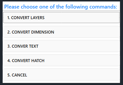
- Convert Layers: Resets entity color, linetype, and lineweight overrides to
ByLayeracross the active drawing. - Convert Dimension: Changes dimensions to match the selected project dimension style.
- Convert Text: Standardizes text entities and multiline text (MText) to the chosen text style.
- Convert Hatch: Normalizes hatch pattern types, scale factors, and layer assignments.
3.4. “Tab Colors” Command (MsTabColors)
When working with many drawings open simultaneously, the Tab Colors tool (MsTabColors) color-codes drawing tabs based on project prefixes or folder locations, making it easy to identify related drawings at a glance.
4. Raster to OLE Panel: Embed Images in DWG
The Raster to OLE tools solve this by embedding raster images directly into the DWG file as OLE objects, making drawings fully self-contained:
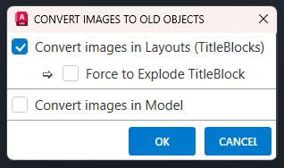
4.1. Global Raster (MsBindRaster)
Scans the entire drawing (Model Space and Layouts), converts all attached raster images into embedded OLE objects, and detaches the original image references. To convert only Model Space images, use the command MsBindRasterModel.
4.2. Single Raster (MsSingleBindRaster)
Prompts you to select a specific raster image in your drawing (such as a signature or stamp) and converts that individual image to an embedded OLE object.
5. Print Panel: Sheet Set Manager & Batch Print
5.1. Create Sheet Set Manager (MSCreateSSM)
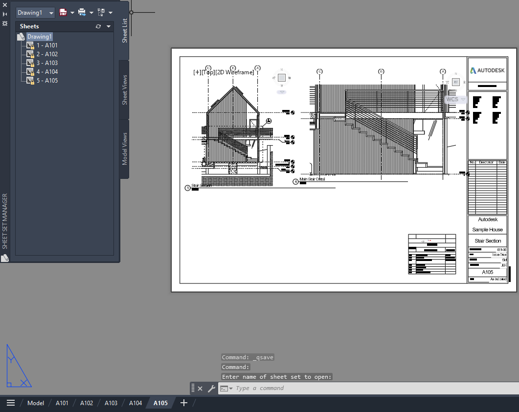
The Create SSM command (MSCreateSSM) scans all active layout tabs in the current drawing and creates an associated AutoCAD Sheet Set (.dst) file in the drawing directory without requiring the manual multi-step AutoCAD wizard.
5.2. Batch Print (MSBatchPrint)
The Batch Print command (MSBatchPrint) automates plotting multiple drawings directly from Model Space or Layout tabs to PDF files or physical plotters.
- Click Batch Print on the ribbon or type
MSBatchPrint. - Configure the plot setup:
- Use an existing Page Setup stored in the DWG, or configure a custom plotter (
.pc3), paper size, plot style (.ctb/.stb), and orientation.
- Use an existing Page Setup stored in the DWG, or configure a custom plotter (
- Select the boundary detection mode:
- Select Block Reference: Automatically detects Title Block references or Xrefs as printable frames.
- Rectangle Frame: Automatically detects rectangular polyline boundaries placed on the
BATCH_PRINT_FRAMElayer.
- Select the plot order (e.g. Left-to-Right, Top-to-Bottom).
- Set the output destination (single multi-page PDF file or individual sheet files) and click Print.
6. License & Language Settings
6.1. License Activation (MsAboutMeMla)
To view license status or enter your activation key, click License on the MLabs ribbon or run MsAboutMeMla. Enter your license key and click activate.
6.2. Multilingual Support (13 Languages)
The plugin supports 13 languages. By default, it automatically detects your AutoCAD language setting. You can also switch languages manually at any time by clicking Language on the ribbon or running MsLanguage:
6.3. Free Trial
A 30-day evaluation trial with access to all features is included upon installation. When your trial ends, enter your license key under MLabs > License to continue using the software.
Command Reference
| Command | Action |
|---|---|
MLABSMCP |
MCP Server Console |
MSMERGE |
Merge DWG Files |
MsExportLayouts |
Layouts to Model Space |
MsImportExcel |
Import Excel to Table |
MSTOOLBOX |
AutoCAD Utility Toolbox |
MsConvertFeature |
Standardize Styles |
MsTabColors |
Tab Color Settings |
MsBindRaster |
Convert Rasters to OLE |
MsCreateSSM |
Create Sheet Set (.dst) |
MSBatchPrint |
Batch Plotting |
MsAboutMeMla |
License Manager |
MsLanguage |
Language Selector |