
Table of Contents
1. Quick Dim Panel
Generate Dimensions
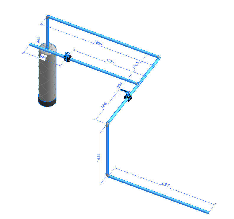
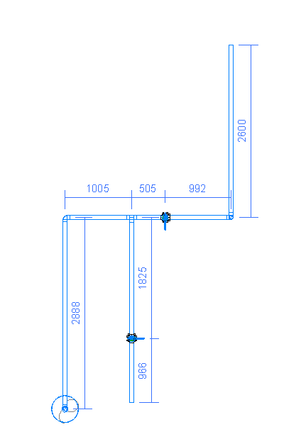
Automatically place accurate dimensions and tags by selecting MEP elements. This tool fully supports pipes, ducts, cable trays, conduits, and fabrication parts.
Flexible Workflows: You can either pre-select elements before executing the command, or trigger the command first and pick elements individually. The plugin handles generation on the fly based on your configured active settings.
Note: You can safely make broad window selections across non-MEP components; the plugin’s built-in filtering engine will isolate the correct elements for you.
This functionality is active and works perfectly across all model views, including 3D views, floor plans, and cross-sections.
Note: If generated dimension lines are positioned too close together, an automated anti-overlap mechanism will clean up and consolidate the layouts, removing overcrowded elements automatically.
Merge Dims
By default, newly generated dimensions are created as separate segments. This utility allows you to instantly merge multiple distinct items into a single, clean, continuous dimension string. Simply select a region; the built-in filter ignores non-dimension elements and automatically combines collinear lines to streamline your sheet presentation.
Purifying
A fast visual clean-up utility window that allows you to selectively batch-delete dimensions, tags, model lines, detail lines, or instantly hide reference planes within the active view or across the entire project.
Settings
Fine-tune automation behavior by adjusting offsets, choosing system family types, tracking fitting inclusions, and configuring dedicated tag styles for pipe and duct runs.
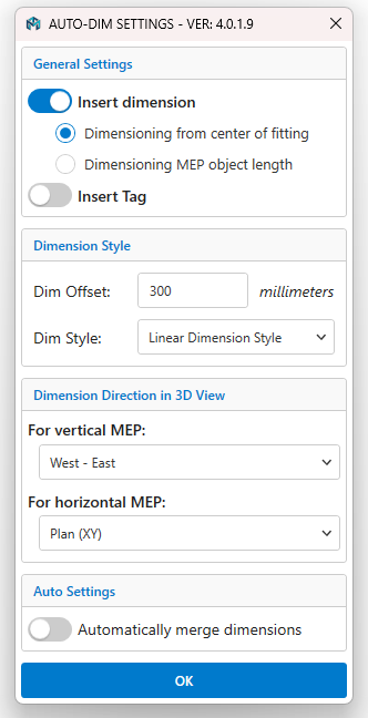
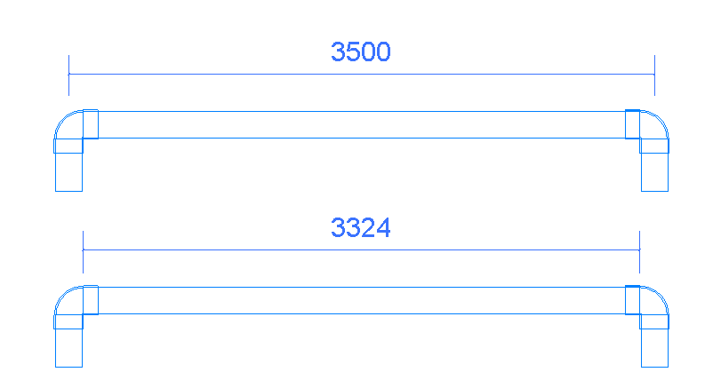
a. Insert Dimensions: Choose whether to pull dimensions directly from the geometric center of fittings or capture the exact linear cut-length of MEP objects.
b. Insert Tag: Seamlessly bind tags during automatic dimension placement. Includes settings to toggle category-specific tag leaders and customize the offset distance between a tag and its host.
c. Dimension Style: Select your preferred active Revit Dimension Type and adjust default placement gaps (Dim Offset) relative to structural components.
d. Dimension Direction in 3D View: Manually pivot or lock the linear plane orientation of dimensions when drafting directly inside 3D environments.
e. Automatically Merge Dimensions: When enabled, individual segments combine automatically into continuous chains right after creation.
2. Tags Panel
Align Vertical By Point
Quickly align messy tag structures vertically. Select multiple tags via a crossing window and pick a layout reference point; the tags shift into a clean vertical line while adjusting leaders gracefully.
Align Horizontal By Point
Align a scattered group of tags along a perfectly horizontal axis. Select the tags, pick your reference target, and let the tool automatically normalize positions without losing host assignments.
Perp. ⊥
Instantly snap tag leader elbows to maintain a crisp, 90-degree perpendicular angle relative to the referenced MEP host line for a highly professional drafting style.
Settings
Configure default selection preferences, text spacings, and automated behaviors for annotation management.
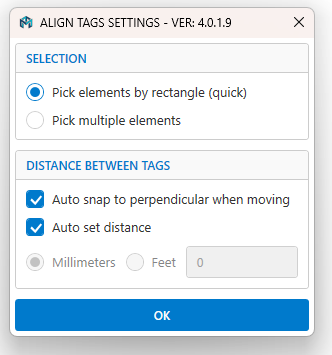
a. Selection Methods: Toggle between drawing an automated bounding rectangle (Pick elements by rectangle) or manually selecting items individually and confirming via the Revit Top-Left “Finish” prompt.
b. Distance Between Tags: Turn on “Auto snap to perpendicular when moving” to instantly format leader elbows on the fly. Enable “Auto set distance” to let the program calculate optimized spacing intervals, or turn it off to manually define custom margins.
3. MEP Tools
Family Browser
Launch a dockable user interface panel to quickly browse, search, filter, and load component families directly into active models using intuitive drag-and-drop mechanics.
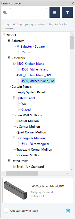
Right-click any component inside the browser to access advanced content menus:
- Family Submenu: Edit families directly inside the Revit Family Editor, trigger batch renaming across all inner types, rename file elements, or select and delete multiple components at once.
- Family Type Submenu: Quick-actions to instantly rename, delete, or duplicate specific family types.
Use the Switch View Mode action button to toggle clean visual thumbnail previews, use Filter Categories to customize visibility by object type, and check Get started with Revit to auto-load the browser window immediately when Revit boots up.
Hangers and Supports
Automatically distribute, align, and array level-based or face-based hangers along structural paths. Works perfectly for parallel or single runs of pipes, ducts, cable trays, and conduits.
Configure custom spacing metrics, define start and end offsets, and lock hanger heights automatically to structural ceiling or floor slab surfaces.
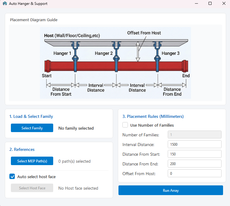
- Select Family: Choose any support or hanger type loaded in your project.
- Select MEP Path(s): Run placement across single or multiple runs simultaneously.
- Select Host Face: The tool automatically identifies and anchors to the nearest overhead element by default, with an option to select reference surfaces manually.
- Placement Rules: Toggle “Use Number of Families” to place an exact count, or rely on automatic interval distance calculations.
Align MEP and Rotate
Align a branch element perfectly perpendicular to a main line in 3D. Simply click a straight main run and select the branch; the branch automatically rotates, slopes, and translates until centerlines intersect precisely in 3D space.
Align MEP
Translate a branch element along the shortest vector path to snap and intersect directly with a main run centerline without changing its current direction, angle, or slope.
Move And Connect
Instantly snap and physically couple components together. Select a fixed equipment instance or fitting, then pick the movable target; the tool shifts and rotates the second component so open connectors merge perfectly.

Bloom
Automatically generate pipe or duct stub extensions from all open ports on equipment or inline accessories. Features a continuous picking mode to speed up initial routing setups.
Elbow 90 & Elbow 45
Generate clean 90-degree or 45-degree angled elbow extensions on selected linear runs using an interactive directional compass menu.
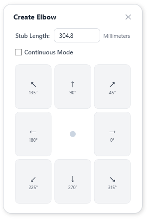
- Stub Length: Set the exact length of the trailing pipe/duct segment following the elbow placement.
- Direction Buttons: Arrow orientations correspond to the workspace. Pick an arrow direction, then click the target element to place the elbow.
- Continuous Mode: Keep drawing elbows consecutively across elements until you exit via the ESC key.
Tap Connect
Connect branch pipes or ducts directly to a main run surface via standard tap fittings. The utility automatically trims, extends, and aligns skewed or offset branches into the main run side-walls. Note: This tool functions flawlessly even if the system’s default routing preferences are not configured for Tap junctions.
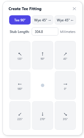
Gen Tee
Split an active linear pipe or duct segment at a clicked point to instantly insert a standard Tee or Wye fitting. A pop-up dialog allows you to set the branch direction, stub length, and choice of fitting family.
MEP Clash
Detect interference issues between select MEP models and target structure categories (fully supports linked RVT models). Includes immediate tools to isolate issues, view comprehensive clash sheets, or automatically place wall/floor sleeves at intersection zones.
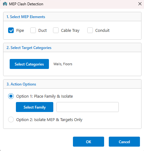
- Option 1: Place structural sleeves and visually isolate them alongside clashing elements.
- Option 2: Isolate clashing items directly for manual routing reviews.
Clash Solver
Resolve interference checks by automatically creating custom bypass routing loops around obstacles with configurable angles (45° or 90°) and safety clearances.
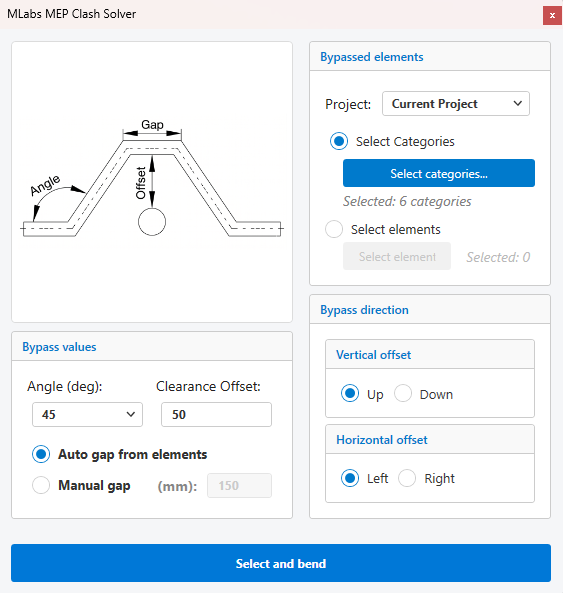
Clearance calculations are managed using an accurate geometric engine formula:
Offset = (Obstacle Outer Boundary - Pipe Centerline) + Pipe Outer Radius + Clearance Offset
- Bypassed Elements: Define target problem categories (Pipes, Ducts, Cable Trays, Conduits, Beams, or Columns) and toggle linked model visibility.
- Bypass Direction: Run routing adjustments Vertically (Up/Down) or Horizontally (Left/Right).
- Bypass Values: Set angles, manage clearance thresholds, and alternate between automatic or manual obstacle gap tracking.
4. MEP Routing
To Connector
Bridge paths between two open ports instantly. Select open connectors on any pipe or duct run; the routing engine automatically calculates and generates a clean orthogonal 3D path with matching elbows. Features a path-cycling option to choose between alternative layout directions.

To Point
Route straight from an open connector to any clicked surface point. Select the connector and pick a point on a wall, floor, or ceiling face (including linked models); the system generates a clean orthogonal segment directly to that coordinate location.
Branch Connect
Connect open connectors directly to a main line run. Select the open connector and pick your main pipe or duct target; the tool maps an orthogonal branch route and locks it into the run with a matching Tee or Tap fitting.

Random Cycle
If an automated routing path (To Connector, To Point, or Branch Connect) doesn’t perfectly match your design preference, use this command to rotate through alternative geometric solutions instantly.
5. MEP System
Assign and Delete System
- Assign: Select a segment run to view a full list of mechanical/piping system types available in your project, allowing you to quickly shift and reassign system classifications.
- Delete: Wipe system data instances off selected items without risk of deleting physical modeling components.
Disconnect
Select two connected components (e.g., a pipe and its matching fitting) to instantly decouple their shared connectors, leaving them physically adjacent but unjoined.
Break
Click two coordinates along a continuous pipe or duct run to instantly cut out and delete the intermediate section while keeping outer runs intact.
Split
Batch-slice straight runs of pipes, ducts, conduits, or cable trays by designating a fixed length interval. The tool splits the geometry and automatically places matching Union fittings at every cut point.
6. MEP Plus
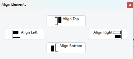
Alignment
Align multiple fittings, equipment instances, or inline components along explicit Left, Right, Top, Bottom, or Elevation alignments based on their exact 3D bounding boxes.
Set Distance
Perfectly position parallel linear components relative to each other using explicit dimension gaps.
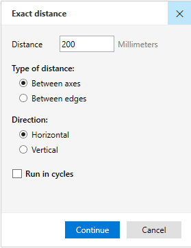
- Distance Field: Input your target spacing. The utility displays a convenient list of recently used values for fast reuse.
- Between Axes: Space elements directly center-to-center.
- Between Edges: Space elements outer-edge to outer-edge.
- Horizontal / Vertical: Restrict spacing rules strictly to horizontal or vertical planes.
- Run in Cycles: Keep the tool active to continuously apply spacing settings across multiple selections without closing the dialog.
MEP Offset
Offset elements by exact distances and directions. Choose whether to move existing components or generate new, parallel offset arrays.
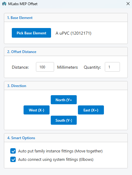
- Pick Base Element: Establish the root reference object to calculate directions and dimensions.
- Quantity & Distance: Set your offset margins and specify how many parallel copies to build.
- Move Together: Automatically preserve and shift complex family instances (like inline valves) during offset adjustments.
- Auto Connect: Intently reconstruct line junctions using active system elbows to keep systems fully connected.
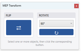
Flip Rotation
Flip loaded components 180 degrees or shift orientation angles across single or batch selections. The panel remains open consistently, allowing you to select and rotate items continuously.
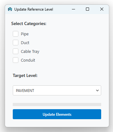
Ref Level
Batch reassign Reference Levels across categories of pipes, ducts, cable trays, or conduits without shifting or changing their physical modeling heights or elevations.
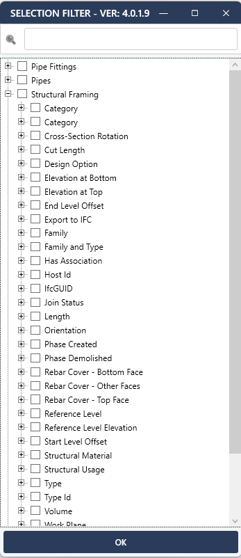
Selection Filter
Refine broad window selections via a clear, hierarchical tree window. Organizes active model selections by Category, parameters, and matching shared values to let you check and isolate items quickly.

MEP Automation Suite
An all-in-one productivity plugin for Autodesk Revit, built to make life easier for MEP professionals.