Tired of manually fixing AutoCAD layers after exporting from Revit? In this comprehensive tutorial, I will show you how to master the Revit layer mapping tool to automate your workflow. We will cover everything from basic category mapping to advanced layer modifiers and external .txt configuration files. Ensure your DWG exports meet professional industry standards every time!
I. Navigating the Revit Layer Mapping Export Setup
To begin, we need to access the DWG Export Settings. Think of this as the “translation dictionary” Revit uses to talk to AutoCAD.
Note: This guide applies to Revit 2025 and newer versions.
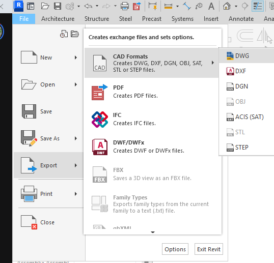
Accessing the Dialog:
- Go to the File tab.
- Select Export > CAD Formats > DWG.
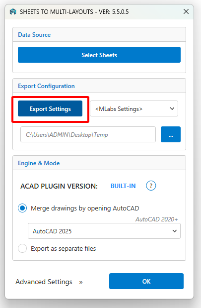
If you are using the MLabs Export Sheets to DWG plugin, simply click the Export Settings button for quick access.
Once the dialog opens, you will see several tabs: Layers, Lines, Patterns, Text & Fonts, Colors, etc. For successful Revit layer mapping, our primary focus is the Layers tab. Here, you have two main components:
- The Category Tree: On the left, you see every Revit category (Walls, Windows, Piping, etc.).
- The Mapping Columns: On the right, you define the Layer Name, Color ID, and Status.
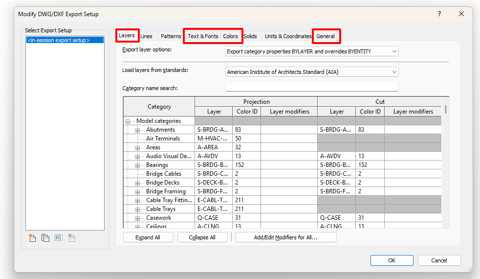
In this guide, we will focus on the most crucial tabs: Layers, Text & Fonts, Colors, and General.
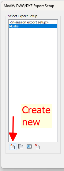
Pro Tip: Always save your setup first so you can easily reuse it in future sessions.
II. Understanding Export Layer Options
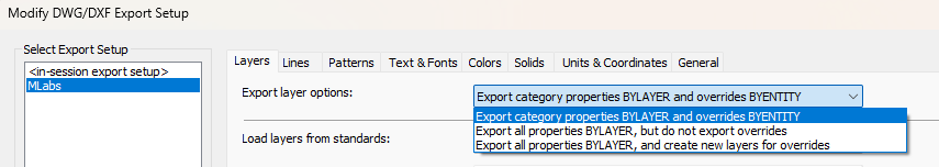
1. Export category properties BYLAYER and overrides BYENTITY
- How it works: This is the default Revit setting. Elements that follow the standard category rules will be set to ByLayer in AutoCAD. However, if you manually changed the color or linetype of a specific element in Revit (using Override Graphics in View), it will be exported as an Entity Override.
- The Result: The DWG will look exactly like your Revit view, but it can be a nightmare for CAD users to manage because they cannot change the colors globally using the Layer Manager.
2. Export all properties BYLAYER, but do not export overrides
- How it works: Revit forces everything to be ByLayer. Any manual graphic overrides you made in your Revit view are completely ignored during the export process.
- The Result: This produces the cleanest, most professional CAD file. It ensures 100% standardization and is the preferred choice when sending backgrounds to consultants who need to Xref your drawings.
- The Catch: If you highlighted a specific wall in red for a reason, that red color will disappear and revert to the default layer color in AutoCAD.
3. Export all properties BYLAYER, and create new layers for overrides
- How it works: This is the “middle ground.” If you have a wall with a red override, Revit won’t put it on the standard wall layer. Instead, it will generate a new layer (e.g.,
A-WALL-Red) so the object can stay “ByLayer” while keeping its unique color. - The Result: You preserve the visual intent of your Revit view without using Entity Overrides. However, be careful—this can lead to “Layer Bloat,” where your CAD file ends up with hundreds of unnecessary layers.
III. Leveraging Industry Standards (Load Layers from Standards)
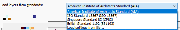
When you click the “Load layers from standards” dropdown, you are presented with the world’s most common CAD drafting standards.
Available Standards in Revit:
- AIA (American Institute of Architects): The most widely used standard in North America and many international projects. It uses a disciplinary prefix (e.g.,
A-for Architecture,S-for Structure). - ISO 13567: An international standard that uses a very structured, numerical, or coded naming system.
- CP83 (Singapore Standard): Specifically tailored for the Singapore construction industry’s e-submission requirements.
- BS 1192 (British Standard): The predecessor to the ISO 19650 framework, common in UK-based workflows.
The “Power User” Option: Load settings from file…
This is the most important option for firm leaders and BIM Managers. Instead of using a generic standard, you can browse to a Custom Text File (.txt) that contains your specific company layer names and colors.
If your company has a specific CAD manual, you should create a master .txt file once. By using “Load settings from file,” every team member can import the exact same Revit layer mapping settings, ensuring 100% consistency across all project sheets.
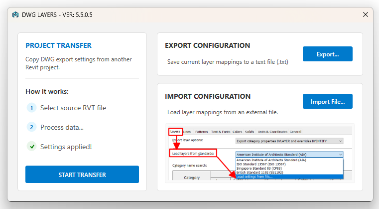
Pro Tip: Using the MLabs “Revit Sheets to DWG” Plugin to Export Layer Settings
To help you easily save your layer mapping to a text file (.txt), you can use the MLabs “Transfer Settings” command. After exporting, you can rapidly modify the text file and import it back into any project as needed.
IV. Customizing the Mapping Table (Manual Edits in Revit)
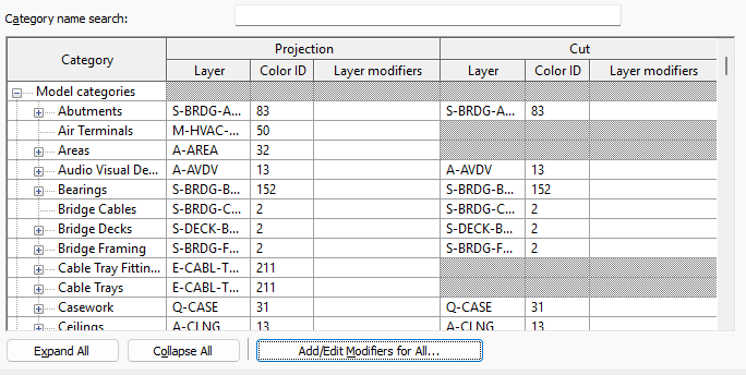
The mapping table is organized into a hierarchy. To make your life easier, use the Category name search at the top to quickly find what you need (e.g., “Wall” or “Door”).
1. Projection vs. Cut
Revit distinguishes between how an object looks when it is “cut” (like a wall in a floor plan) and when it is in “projection” (like a wall seen in an elevation).
- Projection: Controls the layer and color for objects seen from a distance.
- Cut: Controls the layer and color for objects sliced by the view plane.
- Tip: In most cases, you want these to be the same. However, for structural or architectural detailing, you might want “Cut” elements on a heavier or differently colored layer.
2. Changing Layer Names and Color IDs
Simply click into the Layer column to rename it. For the Color ID, enter the desired AutoCAD Index Color (1-255).
- Example: If your CAD template uses Color 7 (White/Black) for thin lines and Color 1 (Red) for thick lines, ensure your Revit categories match this logic.
3. The Power of Layer Modifiers
This is an advanced feature. By clicking in the Layer Modifiers column, you can add dynamic “Suffixes” or “Prefixes” to a layer name based on Revit parameters.
V. Batch Editing the Revit Layer Mapping File with Excel
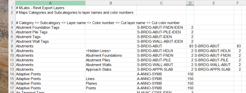
If you already have a Revit layer mapping .txt file, you can open it in Excel immediately for bulk edits. If you don’t have a text file yet, you can use the MLabs app to export your current layer mapping. The structure of the .txt file will look like this:
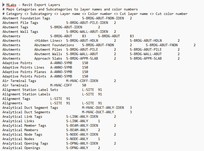
The Revit layer mapping file is a tab-delimited text file, meaning it is perfectly structured for Excel.
How to edit like a Pro:
- Open in Excel: Open Excel, go to File > Open, and select the
.txtfile. Excel will recognize the tabs and organize the data into clean columns:- Column A: Revit Category
- Column B: Revit Subcategory
- Column C: Projection Layer Name
- Column D: Projection Color ID
- Column E/F: Cut Layer and Cut Color
- Bulk Edit: Now you can utilize Excel’s powerful features:
- Find & Replace: Quickly change all “A-WALL” prefixes to “ARC-WALL”.
- Flash Fill: Generate layer names based on specific naming patterns.
- Sorting: Sort by Color ID to ensure your lineweights are consistent across different categories.
- Save Correctly: This is the most important step. When you are finished, you must save the file as Text (Tab delimited) (*.txt). If you save it as an Excel Workbook (
.xlsx), Revit will not be able to read it. - Locate your file in Revit: Click “Load settings from file…” in the Export Setup dialog to browse and import your newly updated
.txtfile.
You can watch the video to see how I quickly modify the: Revit layer mapping file using Excel
VI. Advanced Automation: Using Layer Modifiers
If you have ever wanted your AutoCAD layers to automatically distinguish between “New Construction” and “Existing” elements without manual sorting, this is the tool you need.
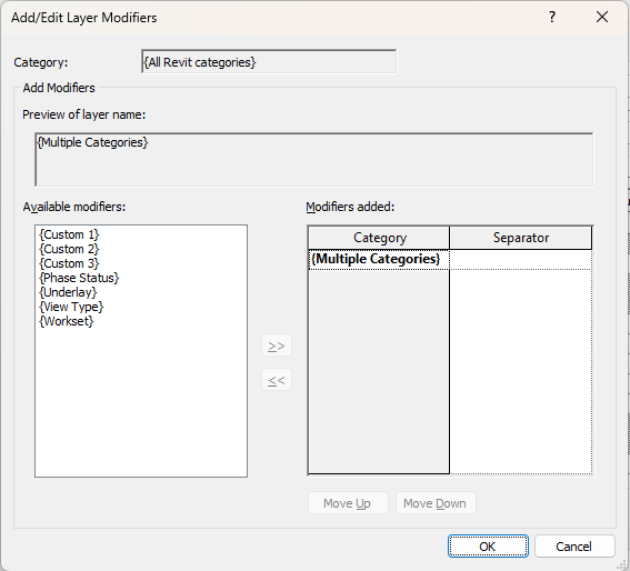
The Add/Edit Layer Modifiers dialog allows you to append specific Revit parameters directly to your CAD layer names.
Commonly Used Modifiers:
- {Phase Status}: Perfect for renovation projects. It adds suffixes like
-EXST(Existing),-DEMO(Demolished), or-NEWto your layers. - {Workset}: Ideal for large-scale projects where you want to separate CAD layers by their Revit Workset (e.g.,
A-WALL-Corevs.A-WALL-Shell). - {View Type}: Useful if you want different layer names for Floor Plans vs. Reflected Ceiling Plans (RCPs).
- {Underlay}: Helps identify elements that are being shown as an underlay in the current view.
The “Custom” Wildcards: You will also see {Custom 1}, {Custom 2}, and {Custom 3}. These provide manual flexibility. You can define these values in the Revit project to create unique naming conventions that are not covered by standard parameters.
Pro Tip: Don’t Forget the Separator! When adding a modifier, always pay attention to the Separator column. If you don’t add a dash (
-) or an underscore (_), your layer name will look likeA-WALLNewinstead ofA-WALL-New. Consistency here is key for meeting CAD standards.
VII. Managing Text Behavior (Visual Fidelity vs. Editability)
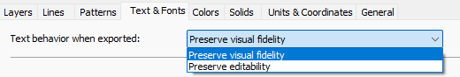
Under the Text & Fonts tab in the Export Setup dialog, you face a crucial choice: do you want the text to look perfect, or do you want it to be easy to edit?
1. Preserve Visual Fidelity
- How it works: Revit prioritizes the exact look and position of the text. To achieve this in AutoCAD, Revit may break a single paragraph into multiple individual text strings or wrap them in ways that mimic Revit’s internal text engine.
- Best for: Final presentation sets where the exact placement of every character is critical, and you do not expect anyone to change the text in AutoCAD.
- The Downside: It can be frustrating for CAD users to edit. If they try to add a word, the line wrapping won’t behave correctly because the text is no longer one cohesive block.
2. Preserve Editability
- How it works: Revit prioritizes creating clean MText (Multiline Text) objects in AutoCAD. It keeps paragraphs together, making it easy for someone to double-click and rewrite the text.
- Best for: Collaborative workflows. If you are sending files to a consultant who needs to add their own notes or modify yours, choose this option.
- The Downside: You might notice slight visual shifts. Because AutoCAD and Revit use different text rendering engines, the line endings or total width of a text box might differ slightly compared to what you see in Revit.
Pro Tip: Always check your Font Mapping in the list below this dropdown. If Revit uses a font that isn’t installed on the CAD machine (like a specific Revit-only SHX font), AutoCAD will replace it with a fallback font. Mapping your Revit fonts to standard Windows fonts (like Arial) ensures visual consistency.
VIII. Mastering Export Colors (Index vs. True Color)
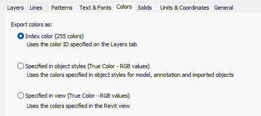
Under the Colors tab, you have three distinct ways to export your project’s colors. Each serves a different purpose depending on your final output goals.
1. Index color (255 colors)
- How it works: This is the industry standard for technical drawings. It maps your Revit categories directly to the AutoCAD Index Color (ACI) system (colors 1–255).
- Best for: Professional deliverables. Most AutoCAD users rely on
.ctbfiles (Color-Dependent Plot Styles) to control line weights. By using Index Colors, your CAD file will seamlessly integrate with existing office plot styles. - The Result: Your lines will have specific, predictable colors that correlate to their intended printing thicknesses.
2. Specified in object styles (True Color – RGB values)
- How it works: Revit uses the exact RGB (Red, Green, Blue) values defined in your Object Styles.
- Best for: High-fidelity coordination where exact branding colors or specific material highlights are required.
- The Downside: True Color ignores standard AutoCAD
.ctbplot styles. If you export a wall as RGB (200, 50, 50), AutoCAD treats it as a “True Color” object, meaning it may not print at the correct thickness if your office uses color-based pen sets.
3. Specified in view (True Color – RGB values)
- How it works: This is the most “visual” option. It takes into account any specific overrides, filters, or transparency settings currently active in your specific Revit view.
- Best for: Presentation exports or colorful diagrams where matching the exact “look” of the Revit view is more important than CAD drafting standards.
IX. The Final Polish: The General Tab
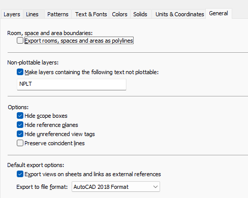
The General tab contains several “quality of life” settings that can make or break the usability of your exported DWG.
1. Room, Space, and Area Boundaries
- Option: Export rooms, spaces and areas as polylines.
- Why use it: By default, Revit doesn’t export room boundaries. If you check this box, Revit creates closed polylines on a specific layer for every room. This is incredibly useful for facility managers or anyone needing to run area calculations directly in AutoCAD.
2. Non-plottable Layers
- The “NPLT” Trick: You can specify a text string (like “NPLT”) so that any layer containing that text will automatically be set to “No Plot” in the AutoCAD Layer Manager. This is perfect for internal notes or construction lines that you want to see on-screen but do not want to print.
3. Cleaning Up the View (Hide Options)
- You should almost always check Hide scope boxes, Hide reference planes, and Hide unreferenced view tags. These are Revit-specific elements. Leaving them on makes your CAD file look messy and unprofessional to someone who doesn’t use Revit.
4. The Xref Decision
- Export views on sheets and links as external references:
- Checked: Revit creates a separate DWG for each view and “Xrefs” them into a master sheet file.
- Unchecked: Revit “binds” everything into a single, flat DWG. This is often the best choice for providing an all-in-one file that is easy to share.
5. File Format
- Always verify which version of AutoCAD your client or consultant is using. Exporting to the AutoCAD 2018 Format is currently the safest standard for compatibility with most modern architectural and engineering offices.